The Raspberry Pi Pico can output a PWM signal to each of its GPIO pins. In this article I will try to use this feature to control a tri-color RGB LED and a servo motor.
PWM on Raspberry Pi Pico
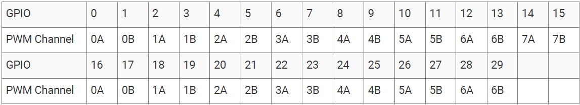
The RP2040 has 8 PWM blocks as shown in the figure below, and each block has two signal outputs, for a total of up to 16 PWM outputs.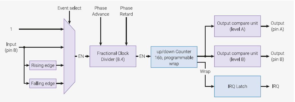
Driving a tri-color RGB LED with a PWM signal
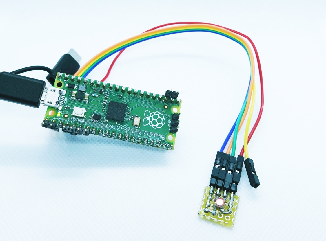
Hardware connections
Below is a wiring diagram of Raspberry Pi Pico’s I/O terminals and LEDs.The tri-color RGB LED used in this project is a LATBT66B from Akizuki Denshi, which is an anode common LED.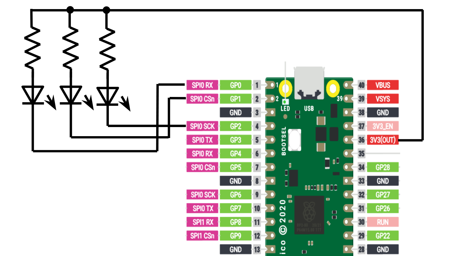
Software (Micro Python code)
We will use Micro Python as before, referring to the documentation for the MicroPython library and checking the examples of the PWM class used for pulse width modulation control. We will mainly use the following functions to set the PWM mode and drive the output.# Create PWM object of specified pin(GP0) pwm_r = PWM(Pin(0)) # Setting PWM frequency pwm_r.freq(100) # Setting PWM duty ratio to duty_u16 / 65535 pwm_r.duty_u16(32768)
Set the PWM settings of GP0, GP1, and GP2 for controlling each LED, and change the display color by changing the duty ratio.
from machine import PWM, Pin
import time

pwm_r = PWM(Pin(0))
pwm_g = PWM(Pin(1))
pwm_b = PWM(Pin(2))
pwm_r.freq(100)
pwm_g.freq(100)
pwm_b.freq(100)

#led_r = 0xFFFF
#led_g = 0x0000
#led_b = 0x0000

def firefly( r, g, b ) :
    led_r = 0xFFFF
    led_g = 0x0000
    led_b = 0x0000

    for i in range(65535) :
        led_r = led_r + r
        led_g = led_g + g
        led_b = led_b + b
        pwm_r.duty_u16(led_r)
        pwm_g.duty_u16(led_g)
        pwm_b.duty_u16(led_b)

while True:
    firefly( 0, 1, 0 )
    firefly( -1, 0,  0 )
    firefly( 0,  0,  1 )
    firefly( 0, -1,  0 )
    firefly( 1,  0,  0 )
    firefly( 0,  0, -1 )
Result
The waveforms D0 to D3 represent the waveforms of the LED output pins, and you can see that the duty cycle of each output is changing as per the program.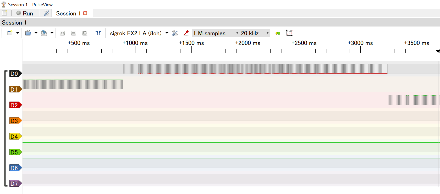
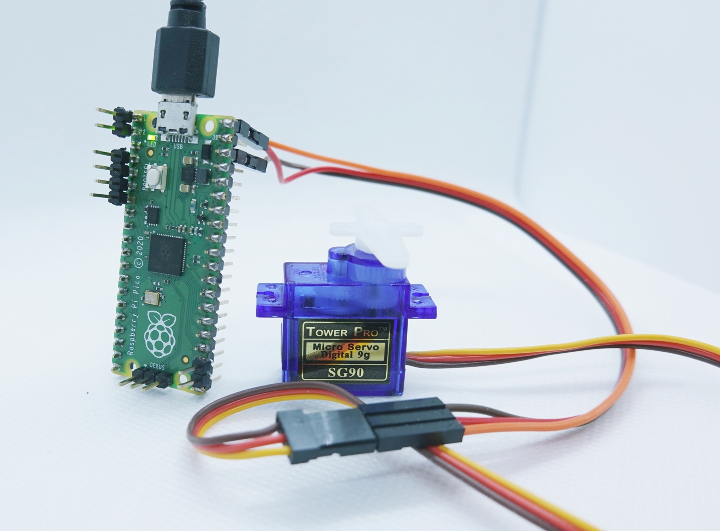
Driving a Servo Motor
Now that I know how to use PWM with Raspberry Pi Pico, I tried to connect a servo motor to it. The servo motor I used is a micro servo SG-90 from Akizuki Denshi.Hardware connection
Software (Micro Python code)
As above, we use the PWM class to control the servo. The servo control method is described in detail on this site, so I used this for the duty cycle and other settings.from machine import PWM, Pin import time pwm1 = PWM(Pin(0)) pwm1.freq(50) i = 0; servo1 = PWM(Pin(0)) servo1.freq(50) max_duty = 65025 dig_0 = 0.0725 #0° dig_90 = 0.12 #90° dig_m90 = 0.025 #-90° while True : servo1.duty_u16(int(max_duty*dig_0)) time.sleep_ms(1000) servo1.duty_u16(int(max_duty*dig_90)) time.sleep_ms(1000) servo1.duty_u16(int(max_duty*dig_0)) time.sleep_ms(1000) servo1.duty_u16(int(max_duty*dig_m90)) time.sleep_ms(1000)
References
PWM class documentation for the MicroPython library (JAPANESE site)【Raspberry Pi Pico】Running servo motors with PWM【MicroPython】 (JAPANESE site)