In the last article, I used Micro Python to control the LEDs on a Raspberry Pi Pico board. Now that we know how to set up the development environment, write the software and program it to the board, we’ll try to use the Raspberry Pi Pico’s various peripherals via the I/O pins on the external header.
LED lighting controll and detection of tact switch
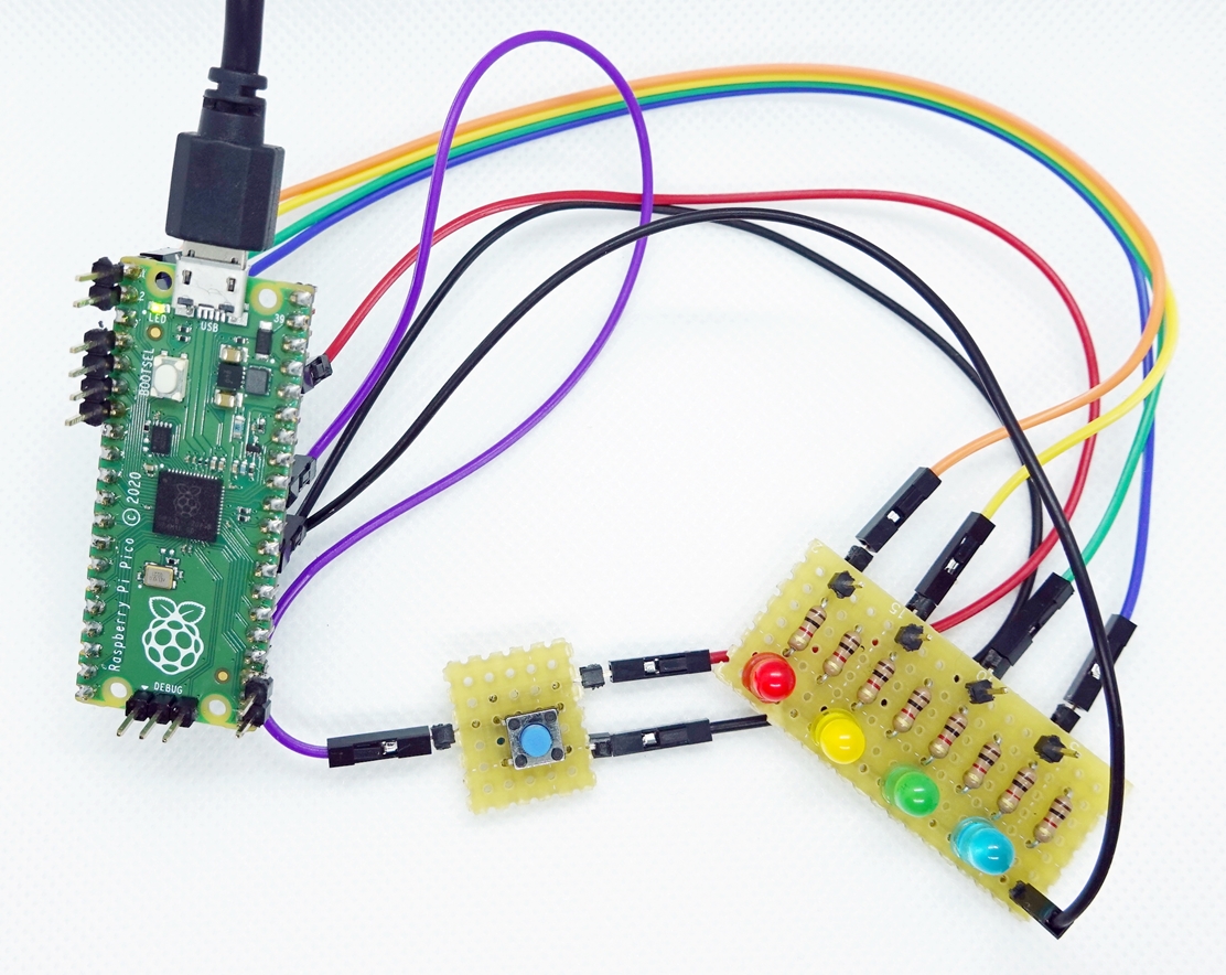
First, as an example of GPIO control, let’s try to control LED lighting (GPIO output) and detect ON/OFF of an external switch (GPIO input). We will also try to use interrupts to detect the GPIO input.Hardware Connection
Below is the wiring for the Raspberry Pi Pico’s I/O terminals, LEDs, and tact switch. The header pins on the board have 26 of the 30 GPIO pins (GP0-GP28) of the RP2040 IC, so you can use any of the pins for the same control.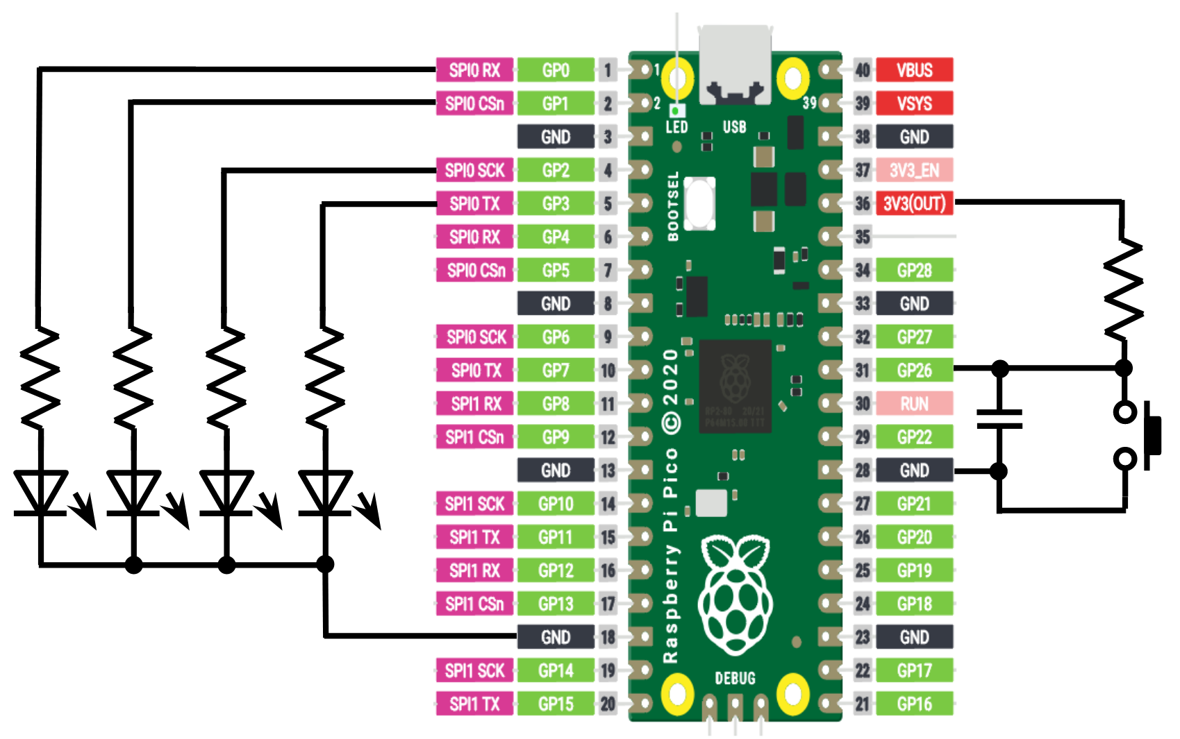
Software (Micro Python code)
As before, we will be using Micro Python. We will refer to the MicroPython library documentation to see an example of how to use the Pin class to control I/O pins while coding. We can use the following functions to set the mode of the I/O pins, drive the outputs, and detect the input values.# Set GP3 as output, Set GP26 as input led_b = Pin(3, Pin.OUT) button = Pin(26, Pin.IN) # Set output L/H led_r.value(0) led_y.value(1) # Setting IRQ callback function button.irq(irq_handle, Pin.IRQ_FALLING)
The following example reads the input value of GP26 and changes the lighting pattern of the LED according to the value.
The following example shows how to set up an interrupt triggered by the GP26 input, detect when GP26 goes low, and change the LED lighting pattern only during that time.from machine import Pin import time led = Pin(25, Pin.OUT) led_r = Pin(0, Pin.OUT) led_y = Pin(1, Pin.OUT) led_g = Pin(2, Pin.OUT) led_b = Pin(3, Pin.OUT) button = Pin(26, Pin.IN) led_r.value(0) led_y.value(0) led_g.value(0) led_b.value(0) while True: if (button.value() == 1) : led_r.value(1) led_y.value(0) led_g.value(0) led_b.value(0) time.sleep_ms(500) led_r.value(0) led_y.value(1) led_g.value(0) led_b.value(0) time.sleep_ms(500) led_r.value(0) led_y.value(0) led_g.value(1) led_b.value(0) time.sleep_ms(500) led_r.value(0) led_y.value(0) led_g.value(0) led_b.value(1) time.sleep_ms(500) else : led_r.value(0) led_y.value(0) led_g.value(0) led_b.value(0) time.sleep_ms(500) led_r.value(1) led_y.value(1) led_g.value(1) led_b.value(1) time.sleep_ms(500)
from machine import Pin
import time

led = Pin(25, Pin.OUT)

led_r = Pin(0, Pin.OUT)
led_y = Pin(1, Pin.OUT)
led_g = Pin(2, Pin.OUT)
led_b = Pin(3, Pin.OUT)

button = Pin(26, Pin.IN)

# IRQ handle function
def irq_handle(p):
    print('Pin state changed', p)
    led_r.value(1)
    led_y.value(1)
    led_g.value(1)
    led_b.value(1)
    time.sleep_ms(1000)

led_r.value(0)
led_y.value(0)
led_g.value(0)
led_b.value(0)
button.irq(irq_handle, Pin.IRQ_FALLING)

while True:
        led_r.value(1)
        led_y.value(0)
        led_g.value(0)
        led_b.value(0)
        time.sleep_ms(500)
        led_r.value(0)
        led_y.value(1)
        led_g.value(0)
        led_b.value(0)
        time.sleep_ms(500)
        led_r.value(0)
        led_y.value(0)
        led_g.value(1)
        led_b.value(0)
        time.sleep_ms(500)
        led_r.value(0)
        led_y.value(0)
        led_g.value(0)
        led_b.value(1)
        time.sleep_ms(500)
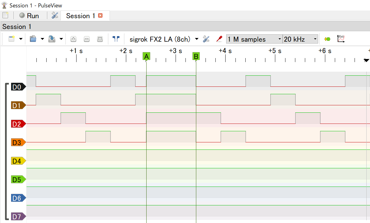
Results
D0 to D3 represent the waveforms of the LED output pins, and it was confirmed that the lighting pattern transitioned correctly as programmed.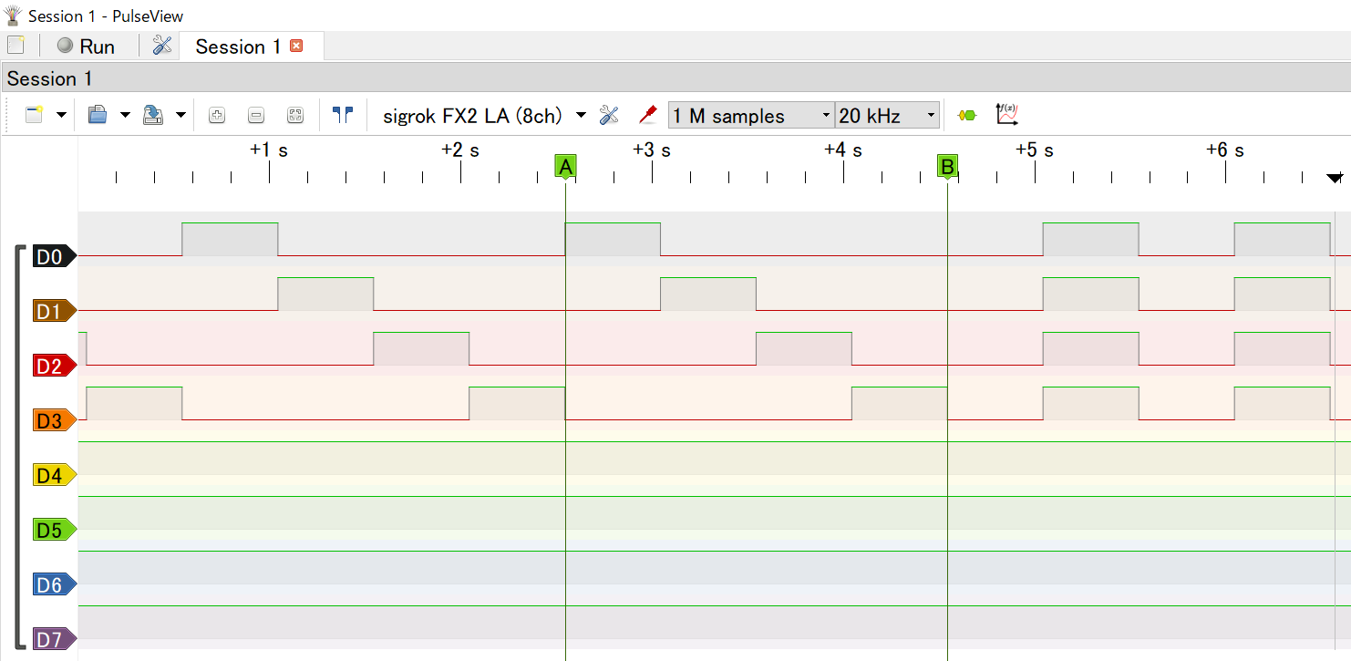
References
MicroPython library documentation (JAPANESE site)Interrupting Raspberry Pi Pico switch operations Memorandum (JAPANESE site)