
Logic Synthesis of RISC-V E203 Core and Writing to FPGA
The first step is to synthesize the RISC-V core (Tang_E203_Mini). Download the necessary files from the following link.https://github.com/riktw/Tang_E203_Mini
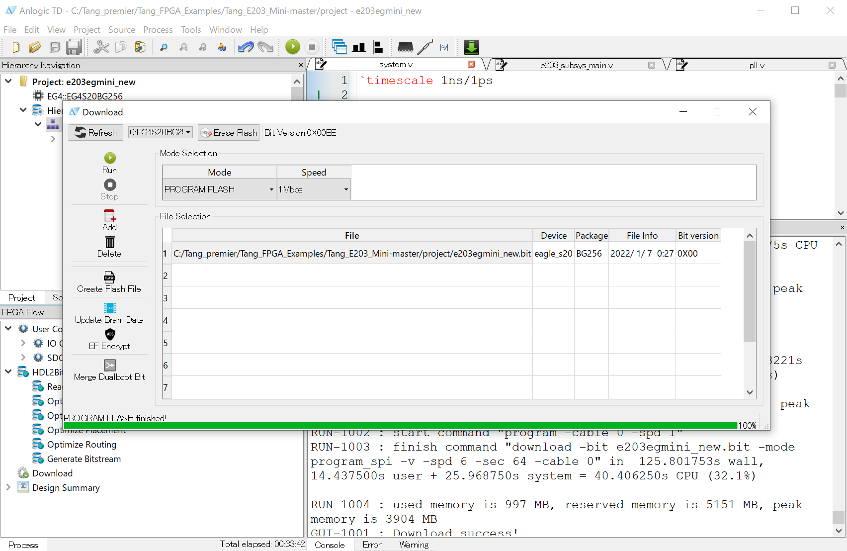
Launch the FPGA development environment TD, open the project file e203egmini_new.al from the Open Project menu, and execute the logic synthesis by clicking Process → Run.
Setting up the software development environment
Next, let’s set up the RISC-V software development environment. This time, we will build software with Arduino IDE and write to Flash using RV debugger and OpenOCD. Therefore, you need to rebuild OpenOCD.Downloading and setting up the Arduino IDE
Download and install the Arduino IDE from the official website below.https://www.arduino.cc/en/software
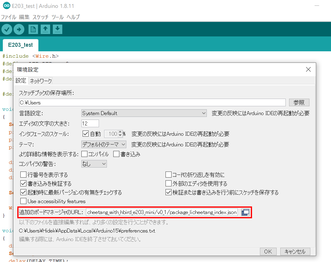
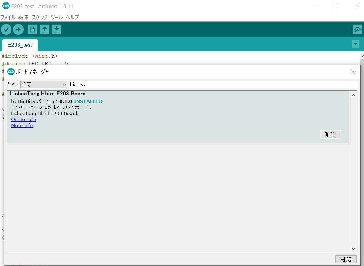
Start the Arduino IDE and add the following URL to the board manager URL in File → Preferences.
https://bigbits.oss-cn-qingdao.aliyuncs.com/Arduino_for_Licheetang_with_hbird_e203_mini/v0_1/package_licheetang_index.json
Setting up the build environment for Open OCD
As mentioned above, we need to rebuild OpenOCD, so we need to set up the build environment (minGW). Get the installer from the following official site and install it.http://www.msys2.org/
After the installation is complete, start MSYS2 MinGW x64 and use the following commands to update the package database.
pacman -Sy
Next, upgrade the packages.
pacman -Su
The next step is to install the development environment (GCC) and other tools required for development.
pacman -S mingw-w64-x86_64-toolchain
pacman -S mingw-w64-x86_64-libusb
pacman -S make autoconf automake
pacman -S libtool mingw-w64-x86_64-libftdi git
Obtaining and building the openocd source for LicheeTang
Now that the setup of the development environment has been completed, we will obtain the openocd source and build it. Create an appropriate directory for development, and execute the following command in the directory to obtain the openocd source for LicheeTang.
git clone https://github.com/Lichee-Pi/LicheeTang_openocd.git
./bootstrap
CFLAGS=-D_FTDI_DISABLE_DEPRECATED CFLAGS=-Wno-stringop-overflow ./configure
make
You are now ready to use the ArduinoIDE to develop software for the LicheeTang RISC-V (E203).
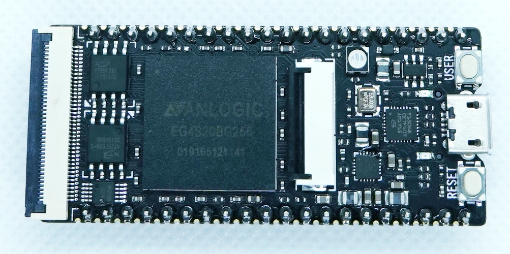
Connection between RV Debugger and TANG PriMER board
Connect JTAG / UART between RV debugger for writing programs and TANG PriMER board. Corresponding pins are as follows.| Lichee Tang Pin | RV |
|---|---|
| H13 (U0_Tx) | Tx |
| J13 (U0_Rx) | Rx |
| C9 (TMS) | TMS |
| B6 (TDI) | TDI |
| C5 (TCK) | TCK |
| A4 (TDO) | TDO |
| G (GND) | GND |
Creating and Writing Programs
Create and write the following program on the ArduinoIDE.
#define LED_RED 9
#define LED_BLUE 10
#define LED_GREEN 11
#define DELAY_TIME 100

void setup()
{
  Serial.begin(9600);

pinMode(LED_RED, OUTPUT);
  pinMode(LED_BLUE, OUTPUT);
  pinMode(LED_GREEN, OUTPUT);
  digitalWrite(LED_RED, HIGH);
  digitalWrite(LED_BLUE, HIGH);
  digitalWrite(LED_GREEN, HIGH);
  Serial.println("===== Blink Test =====");
}

void loop()
{
  digitalWrite(LED_RED, LOW);
  Serial.println("RED : ON");
  delay(DELAY_TIME);
  digitalWrite(LED_RED, HIGH);
  Serial.println("RED : OFF");
  delay(DELAY_TIME);
  digitalWrite(LED_BLUE, LOW);
  Serial.println("BLUE : ON");
  delay(DELAY_TIME);
  digitalWrite(LED_BLUE, HIGH);
  Serial.println("BLUE : OFF");
  delay(DELAY_TIME);
  digitalWrite(LED_GREEN, LOW);
  Serial.println("GREEN : ON");
  delay(DELAY_TIME);
  digitalWrite(LED_GREEN, HIGH);
  Serial.println("GREEN : OFF");
  delay(DELAY_TIME);
}
References
I used the following as a reference.http://galaxystar.image.coocan.jp/tangprimer.htm
https://ameblo.jp/takeoka/entry-12607107193.html
https://qiita.com/Nanchite4618/items/62ff04e3345519b3a939
https://blog.csdn.net/u013507936/article/details/86737964