Using Sipeed TANG PriMER [3] – I2C / SPI with RISC-V

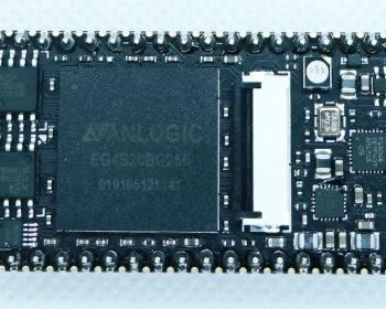
In the previous article, I wrote the RISC-V core on the FPGA and set up the environment to develop software with Arduino IDE. In this article, I will try to control the I/O of this RISC-V processor to run external devices. TANG PriMER FPGA Development Board Try to use SPI First, let’s use the SPI interface. The device to be connected is the EEPROM made by ROHM, which was used in this article.BR25L320 device Hardware The I/O pins on the TANG PriMER board correspond to the SPI signals as shown below. Note that only the SPI MOSI signal is not connected to the 2.54mm pitch pins on the board, and needs to be pulled out from the outer half-pitch header. Also, the SPI CS signal is implemented using GPIOs as shown in the program below. Software The following program is built on the ArduinoIDE to confirm that the EEPROM address

Read more

Using Sipeed TANG PriMER [2] – RISC-V development with Arduino IDE

In the previous article, we have set up the environment of the TANG PriMER FPGA development board from SiPeed, and have confirmed the logic synthesis and writing of the samples. In this article, we will start to synthesize the RISC-V processor, write it to the FPGA, build the software using Arduino IDE, and write it to the ROM on the board. TANG PriMER FPGA development board Logic Synthesis of RISC-V E203 Core and Writing to FPGA The first step is to synthesize the RISC-V core (Tang_E203_Mini). Download the necessary files from the following link. https://github.com/riktw/Tang_E203_Mini Launch the FPGA development environment TD, open the project file e203egmini_new.al from the Open Project menu, and execute the logic synthesis by clicking Process → Run. Setting up the software development environment Next, let’s set up the RISC-V software development environment. This time, we will build software with Arduino IDE and write to Flash using

Read more

Trying Sipeed TANG PriMER [1] – Setting up the development environment

I got a TANG PriMER FPGA development board from SiPeed in China. This page describes the setup and usage of the environment. Sipeed TANG PriMER FPGA Development Board The Sipeed TANG PriMER FPGA Development Board is a small FPGA development board equipped with an Anlogic EG4S20 FPGA, supporting the Hummingbird RISC-V softcore. The main hardware specifications are as follows – FPGA: EG4S20BG256 Logic unit: 20K (LUT4/LUT5 hybrid architecture) – SRAM: approx. 130KB – SDRAM: 64Mb – Flash: FPGA configuration flash, 8Mbit user flash, nor/nand option – Download & debug: On-board FPGA JTAG download debug (RV debug is used for hummingbird core debug) – Interface: FPC40P socket, RGB LCD, nor/nand — FPC40P socket, RGB LCD, can be connected to VGA adapter board — FPC24P socket, connectable to DVP camera, high speed ADC module — Resistive touch screen (RGB LCD) controller (I2C communication) Download and setup the IDE Download the IDE from

Read more

Using the Raspberry Pi Pico [6] – SPI communication with Micro Python

SPI on the Raspberry Pi Pico The RP2040 has two independent SPI controllers (SPI0 / SPI1), available on the Raspberry Pi Pico from GP[0] to GP[27] pins. In this article, I tried to use this feature to connect the LCD display and read/write the EEPROM. Connecting the ATM0130B3 LCD The ATM0130B3 is a 240x(RGB)x240 1.3-inch full-color graphic LCD. This time, we used Akizuki’s control kit with 2.54mm pitch conversion board to connect it. The pitch conversion board also has a level conversion circuit, so it can be connected directly to the Raspberry Pi Pico. 1.3-inch full-color graphic LCD display Hardware connections The following figure shows the wiring between Raspberry Pi Pico’s I/O terminals and the ATM0130B3 conversion board. All the necessary components are mounted on the board. Connect the four SPI pins /CS, D/C, and RES, and the power supply and GND pins, respectively. Schematics Connection Software (Micro Python code)

Read more

Using the Raspberry Pi Pico [5] – I2C communication with Micro Python

I2C on the Raspberry Pi Pico The RP2040 has two independent channels of I2C controllers (I2C0 / I2C1), which are available on the Raspberry Pi Pico from GP[0] to GP[27] pins. In this article, we tried to use this feature to read and write the digital temperature sensor and EEPROM. Connecting the TMP102 digital temperature sensor module The TMP102 device is a high-precision digital temperature sensor made by TI, with a built-in 12-bit ADC, a minimum resolution of 0.0625°C, and an accuracy of ±0.5°C without calibration or signal conditioning by external components. Here, we will use a SparkFun modulewith this temperature sensor IC and peripheral components (I2C pull-up resistor, etc.) to connect to a Raspberry pi pico. TMP102 Module Hardware connection The wiring between the Raspberry Pi Pico I/O terminals and the TMP102 module is shown below, and the I2C pull-up resistor and other necessary components are already mounted on

Read more

Using the Raspberry Pi Pico [4] – A/D conversion with Micro Python

The Raspberry Pi Pico has four analog inputs. In this article we will use this feature to measure the analog input voltages of the terminals and to measure the internal temperature. ADC in Raspberry Pi Pico The RP2040 has an internal A/D converter, which is connected to the external input pins GPIO[26] to GPIO[29] and the internal temperature sensor as shown in the figure below. The A/D converter is a 12-bit SAR type with a sampling rate of 500kS/s when using a 48MHz clock. ADC in Raspberry Pi Pico A/D conversion of an external analog voltage input Hardware connections Below is the connection between the I/O pins of the Raspberry Pi Pico. 3.3V supply voltage is divided by a variable resistor, and the voltage between the tap and GND is input to the ADC0 pin. Schematics Connection Software (Micro Python code) As before, we will use Micro Python. Referring to

Read more

Using the Raspberry Pi Pico [3] – PWM output with Micro Python

The Raspberry Pi Pico can output a PWM signal to each of its GPIO pins. In this article I  will try to use this feature to control a tri-color RGB LED and a servo motor. PWM on Raspberry Pi Pico The RP2040 has 8 PWM blocks as shown in the figure below, and each block has two signal outputs, for a total of up to 16 PWM outputs. PWM on Raspberry Pi Pico Each PWM block output is connected to a GPIO pin as shown in the correspondence below, so the Raspberry Pi Pico has PWM outputs available on all GPIO pins. Mapping of PWM outputs to GPIO pins Driving a tri-color RGB LED with a PWM signal Hardware connections Below is a wiring diagram of Raspberry Pi Pico’s I/O terminals and LEDs.The tri-color RGB LED used in this project is a LATBT66B from Akizuki Denshi, which is an anode

Read more

Using the Raspberry Pi Pico [2] – GPIO I/O with Micro Python

In the last article, I used Micro Python to control the LEDs on a Raspberry Pi Pico board. Now that we know how to set up the development environment, write the software and program it to the board, we’ll try to use the Raspberry Pi Pico’s various peripherals via the I/O pins on the external header. LED lighting controll and detection of tact switch First, as an example of GPIO control, let’s try to control LED lighting (GPIO output) and detect ON/OFF of an external switch (GPIO input). We will also try to use interrupts to detect the GPIO input. Hardware Connection Below is the wiring for the Raspberry Pi Pico’s I/O terminals, LEDs, and tact switch. The  header pins on the board have 26 of the 30 GPIO pins (GP0-GP28) of the RP2040 IC, so you can use any of the pins for the same control. Schematics Connection Software

Read more

Getting started Raspberry Pi Pico [1] – LED blinking with MicroPython

I got a new model of the Raspberry Pi series released in 2021, Raspberry Pi Pico, and tried it. Raspberry Pi Pico is a development board equipped with RP2040 microcontroller which is the dual ARM Cortex M0+ core, originally developed by the Raspberry Pi Foundation. Unlike the conventional Raspberry Pi, it cannot be equipped with Linux OS and can be developed with C / C ++ or MicroPython. First, I tried to build a development environment with MicroPython. Preparation The Raspberry Pi Pico I got was a board only (no accessories such as USB cable included), so I needed to prepare a USB cable (the board side connector is USB micro). Also, download and install “Thonny Python IDE” from the official website as a software (MicroPython) development environment. How to use 1, First, hold down the BOOTSEL button on the board and connect the Rasberry Pi Pico to your PC

Read more