
Try to use SPI
First, let’s use the SPI interface. The device to be connected is the EEPROM made by ROHM, which was used in this article.BR25L320 device
Hardware
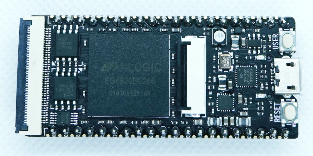
The I/O pins on the TANG PriMER board correspond to the SPI signals as shown below. Note that only the SPI MOSI signal is not connected to the 2.54mm pitch pins on the board, and needs to be pulled out from the outer half-pitch header. Also, the SPI CS signal is implemented using GPIOs as shown in the program below.| Lichee Tang Pin | SPI signal |
|---|---|
| B14 | SCLK |
| B10 | MISO |
| P4 | MOSI |
Software
The following program is built on the ArduinoIDE to confirm that the EEPROM address 0x01AB is read after writing data 0xAA. The CS, WP, and HOLD signals of EEPROM are implemented with E203 GPIO.
#include <SPI.h>

const int SPI_CS   = 2;
const int SPI_WP   = 3;
const int SPI_HOLD = 4;

void setup()
{
  pinMode(SPI_CS,   OUTPUT);
  pinMode(SPI_WP,   OUTPUT);
  pinMode(SPI_HOLD, OUTPUT);
  digitalWrite(SPI_CS,   HIGH);
  digitalWrite(SPI_WP,   LOW);
  digitalWrite(SPI_HOLD, LOW);

Serial.begin(19200);
while (!Serial);

SPI.begin();
}

void loop()
{
  byte data[5];
  data[0] = 0x06;
  spi_write_byte(data, 1);

data[0] = 0x02;
  data[1] = 0x01;
  data[2] = 0xAB;
  data[3] = 0xAA;
  spi_write_byte(data, 4);

data[0] = 0x04;
  spi_write_byte(data, 1);

delay(100);

data[0] = 0x03;
  data[1] = 0x01;
  data[2] = 0xAB;
  spi_read_byte(data, data, 3);

Serial.println(data[3], HEX);

delay(2000);           // wait  seconds for next scan
}

void spi_read_byte(byte *wdata, byte *rdata, byte length)
{
    int i;

digitalWrite(SPI_CS,   LOW);
  digitalWrite(SPI_WP,   HIGH);
  digitalWrite(SPI_HOLD, HIGH);

for( i = 0; i < length; i++ ) {<br />
    SPI.transfer( wdata[i] );
  }
  rdata[i] = SPI.transfer( 0x00 );

digitalWrite(SPI_CS,   HIGH);
  digitalWrite(SPI_WP,   LOW);
  digitalWrite(SPI_HOLD, LOW);

return rdata[i];
}

void spi_write_byte(byte *data, int length)
{
  int i;
  digitalWrite(SPI_CS,   LOW);
  digitalWrite(SPI_WP,   HIGH);
  digitalWrite(SPI_HOLD, HIGH);

for( i = 0; i < length; i++ ) {
    SPI.transfer( data[i] );
  }

digitalWrite(SPI_CS,   HIGH);
  digitalWrite(SPI_WP,   LOW);
  digitalWrite(SPI_HOLD, LOW);
}
Try to use I2C
Next, I would like to try using I2C, but currently the hardware I2C of the E203 is not supported by the Arduino IDE, and it seems that the only way to implement it is with software I2C (The I2C circuit seems to be implemented in the RTL of the E203, so I would like to try it in a different environment later.The following is an example of an implementation using software I2C functions. The device to be connected is the TMP102 temperature sensor used in the following article.
Hardware
The I/O pins and I2C signals on the TANG PriMER board are matched as follows. Since this is a software I2C, the pins to be used can be set by software.| Lichee Tang Pin | I2C signal |
|---|---|
| J11 | SCL |
| F16 | SDA |
Software
Create the following program on the ArduinoIDE and write it.
#include <SlowSoftWire.h>

SlowSoftWire Wire = SlowSoftWire(18, 19, true);

void setup()
{
  Wire.begin();

Serial.begin(19200);
  while (!Serial);<br />
  Serial.println("nI2C Scanner");
}

void loop()
{
  byte error, address;
  byte tmp102 = 0;
  int nDevices;

Serial.println(F("Scanning I2C bus (7-bit addresses) ..."));

nDevices = 0;
  for(address = 1; address < 127; address++ ) {
    // The i2c_scanner uses the return value of
    // the Write.endTransmisstion to see if
    // a device did acknowledge to the address.
    Wire.beginTransmission(address);
    error = Wire.endTransmission();

if (error == 0) {
    Serial.print(F("I2C device found at address 0x"));
    if (address<16)
      Serial.print(F("0"));
    Serial.print(address, HEX);
    Serial.println(F("  !"));

nDevices++;

if(address == 0x48) {
  tmp102 = 1;
}
else {
  tmp102 = 0;
}

}
else if (error==4) {
    Serial.print(F("Unknown error at address 0x"));
    if (address<16)
      Serial.print("0");
    Serial.println(address,HEX);
}

}

if (nDevices == 0) {
    Serial.println("No I2C devices foundn");
  }
  else {
    Serial.println("donen");

if(tmp102 == 1) {
  uint8_t data[2];
  Wire.requestFrom(0x48, 2, 1);
  data[0]= Wire.read();
  data[1]= Wire.read();
  Serial.print(F("TMP102 data : 0x")); Serial.print(data[0], HEX); Serial.print(F(" 0x"));  Serial.print(data[1], HEX);
  Serial.println(F(""));
}

}

delay(2000);           // wait 2 seconds for next scan
}
References
https://qiita.com/Nanchite4618/items/62ff04e3345519b3a939