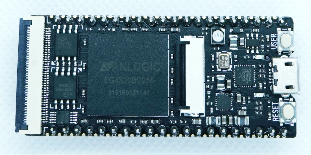
I got a TANG PriMER FPGA development board from SiPeed in China. This page describes the setup and usage of the environment.
Sipeed TANG PriMER FPGA Development Board
The Sipeed TANG PriMER FPGA Development Board is a small FPGA development board equipped with an Anlogic EG4S20 FPGA, supporting the Hummingbird RISC-V softcore.
The main hardware specifications are as follows
– FPGA: EG4S20BG256
Logic unit: 20K (LUT4/LUT5 hybrid architecture)
– SRAM: approx. 130KB
– SDRAM: 64Mb
– Flash: FPGA configuration flash, 8Mbit user flash, nor/nand option
– Download & debug: On-board FPGA JTAG download debug (RV debug is used for hummingbird core debug)
– Interface: FPC40P socket, RGB LCD, nor/nand
— FPC40P socket, RGB LCD, can be connected to VGA adapter board
— FPC24P socket, connectable to DVP camera, high speed ADC module
— Resistive touch screen (RGB LCD) controller (I2C communication)
Download and setup the IDE
Download the IDE from the Sipeed download site below. The latest version of the IDE for Windows is r4.6.4. Also, download the license file with .lic extension (currently named “Anlogic_20220703.lic”), as it is required to run the tool. After installation, place it in the license folder under the installation folder.
http://dl.sipeed.com/TANG/Primer/IDE
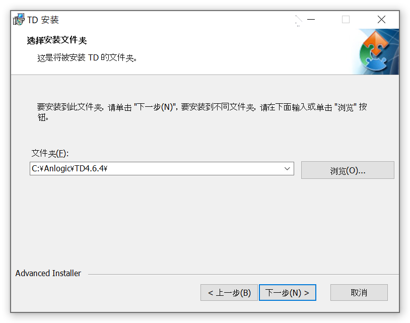
Double-click on the downloaded executable to proceed with the installation. The guide is all in Chinese, but you can install it without any problems by specifying the installation location and clicking “安装” (install). (“下一歩” means “Next” and “上一歩” means “Back”.)
Starting the IDE
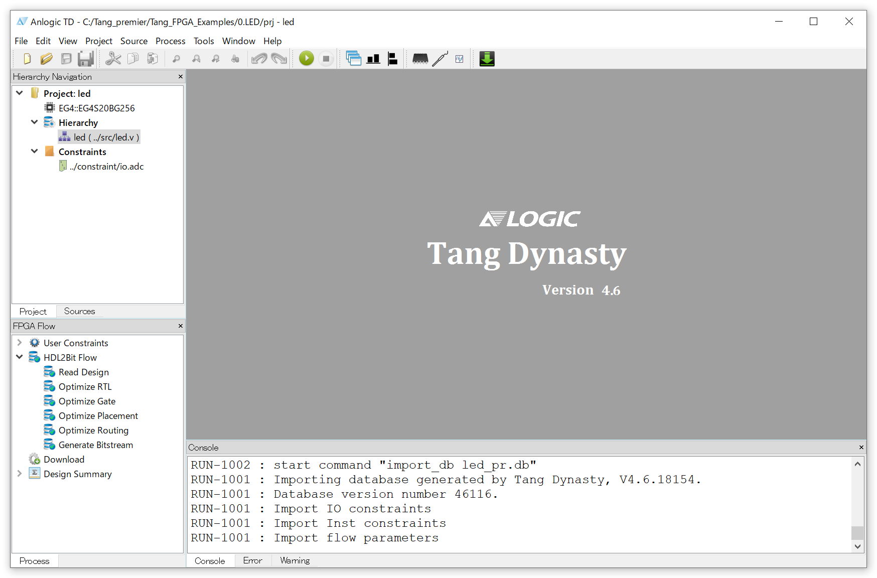
The following is the startup screen.
Let’s start with a sample to see the basic usage. You can download the sample project from the following link.
https://github.com/Lichee-Pi/Tang_FPGA_Examples
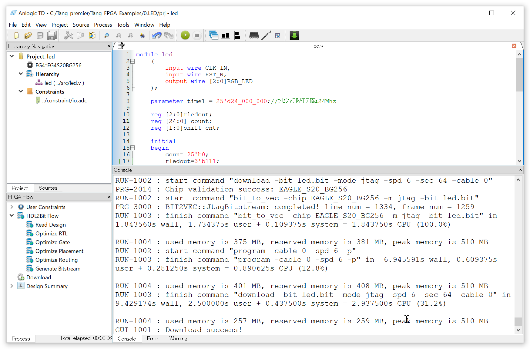
From the File menu, open the file led.al in the 0.LED -> prj folder among the files you just downloaded. This will be the project file.
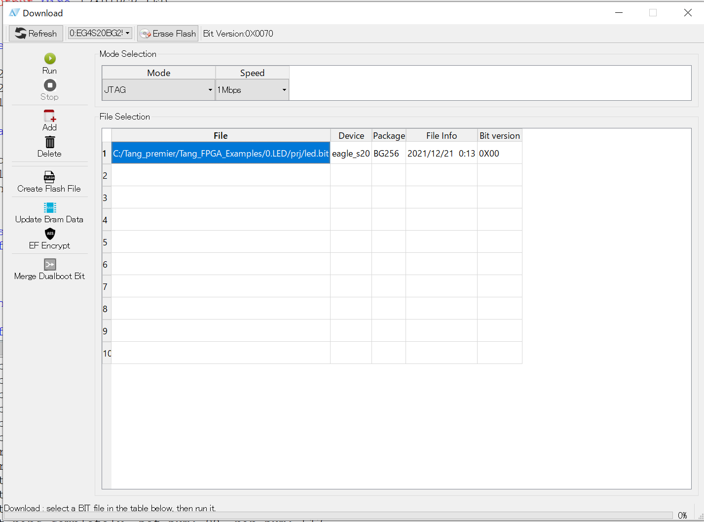
After editing the Verilog HDL code led.v as necessary, save the file and select Run from the Process menu to execute logic synthesis and generate the binary file led.bit. After successful synthesis, select Download from the Tools menu, and start the programmer as shown below.
After confirming that the device is correctly recognized and the binary file for writing is loaded, click the Run button to write the data on the board. The full-color LED on the board should blink.
References
Tang Primer:Designing RISC-V with Chinese FPGA (JAPANESE site)
